Published: 06-06-2016
Overview
The goal is to develop some code that can be used to automatically generate the G-code for milling holes. As explained briefly in part 5, the best way to mill holes is to use helical ramping followed by a spiralling motion. Manually writing G-code to do this for each hole would become a nightmare quickly, so we want to automate it.
Hole milling process
For a given hole diameter, first, a helical ramping motion is used to create a small hole in the center. The path of this helical ramp depends on the size of the end mill. To clear all the material the helical top-down radius should be no bigger than the diameter of the end mill. The number of helical turns should be specified by the depth cut rate. After milling the helix, the cutter should follow a spiral out to the hole diameter, or just less (for a final profiling). This should be done at some specified spiral step rate. This helical and spiraled cutting should then be repeated for each cutting pass. Multiple passes are needed to cut thick materials.
When cutting the end mill size must be taken into consideration. It can't just follow the zero thickness path we will be generating otherwise the hole will be over-sized. The helical ramping and spiral paths must be offset to compensate for this. To keep things simple all the G-code generated first will not have any offsets. These functions will then be wrapped by a 'master function' which calculate the necessary offsets. This help remove complication bloaty code from the ramping/spiral functions and makes them easier to understand.
Generating a helical cut
To generate a helical ramp a circle must be drawn via two arcs and combined with some Z-axis movement. This creates a 360 degree helix which can be called multiple times for more rotations. As a refresher the G-code command for an arc is:
$$G2 \ X \ Y \ Z \ I \ J $$
'G2' specifies the arc is clockwise, 'G3' would be used for a anti-clockwise. 'X' and 'Y' set the arc end points. 'Z' is used to create a helix by adding an extra linear motion in the Z-axis.
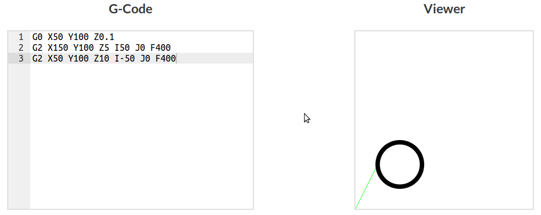
The first job is to create a basic helical ramping function. When called it will generate the code for one revolution (360 degrees) of a helical ramp.
function helicalRamp360(center: Pos, radius: number, clockwise: boolean, start_z: number, end_z: number): string[] {
	var commands: string[] = [];

	var half_z: number = (start_z + end_z) / 2.0;
	var motion = clockwise ? 'G2' : 'G3';

	commands.push(`G0 X${center.x - radius} Y${center.y} Z${start_z + 0.1}`);
	commands.push(`${motion} X${center.x + radius} Y${center.y} Z${half_z} I${radius} J0 F400`);
	commands.push(`${motion} X${center.x - radius} Y${center.y} Z${end_z} I-${radius} J0 F400`);

	return commands;
}

var start = { x: 100.0, y: 100.0 };
console.log(helicalRamp360(start, 50, true, 0, 10).join('\n'));

// G0 X50 Y100 Z0.1
// G2 X150 Y100 Z5 I50 J0 F400
// G2 X50 Y100 Z10 I- 50 J0 F400
Generating a spiral
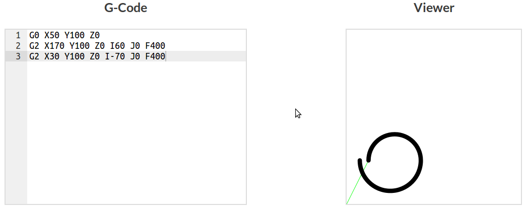
To generate a spiral two arcs are drawn with increasing radii. This creates an unclosed 360 spiral which can be called multiple times for more rotations. An extra argument/parameter should be used to close the spiral, making it circular again.
function spiral360(center: Pos, start_radius: number, end_radius: number, clockwise: boolean, z: number, finish = false) {
	var commands: string[] = [];
	var motion = clockwise ? 'G2' : 'G3';

	commands.push(`G0 X${center.x - start_radius} Y${center.y} Z${z}`);
	commands.push(`${motion} X${center.x + end_radius} Y${center.y} Z${z} I${(start_radius + end_radius) / 2.0} J0 F400`);
	commands.push(`${motion} X${center.x - end_radius} Y${center.y} Z${z} I-${(end_radius)} J0 F400`);
	if (finish) {
		commands.push(`${motion} X${center.x + end_radius} Y${center.y} Z${z} I${(end_radius)} J0 F400`);
	}

	return commands;
}

var start: Pos = { x: 100.0, y: 100.0 };
console.log(spiral360(start, 50, 70, true, 0, false).join('\n'));

// G0 X50 Y100 Z0
// G2 X170 Y100 Z0 I60 J0 F400
// G2 X30 Y100 Z0 I- 70 J0 F400
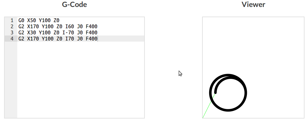
Setting the functions final argument to 'true' returns the generated code for a closed spiral. This is import for finishing off spiral with multiple turns, making it circular again.
var start:Pos = { x:100.0, y:100.0 };
console.log(spiral360(start, 50, 70, true, 0, true).join('\n'));

// G0 X50 Y100 Z0
// G2 X170 Y100 Z0 I60 J0 F400
// G2 X30 Y100 Z0 I-70 J0 F400
// G2 X170 Y100 Z0 I70 J0 F400
The code here might look a bit different, that's because it's written in Typescript. All the arguments/parameters are typed which aids debugging or generally prevents stupid errors. Most are just basic types but the 'Pos' type is self defined. Below is the interface used to describe this type.
interface Pos{
	x: number;
	y: number;
	z?: number;
}
Now these basic function can be leveraged by higher order functions to create helical ramps and spirals with multiple revolutions depending on how much material can be cut on each pass.
Higher order helical and spiral functions
To make these simple functions useful we need to extrapolate them with higher order functions. These higher order functions will be used to generate code for multiple helical and spiral rotations, as needed when milling holes.
function spiralFull(center: Pos, start_radius: number, end_radius: number, spiral_step: number, clockwise: boolean, z: number, finish = false): string[] {
// Spirals from start_radius to end_radius with step size spiral_step
var commands: string[] = [];
var spiral_number:number = Math.ceil((end_radius - start_radius) / spiral_step);
var current_radius: number = start_radius;
var next_radius: number = current_radius + spiral_step;
// Loop through spirals
for (var i = 0; i < spiral_number - 1; ++i) {
commands = commands.concat(spiral360(center, current_radius, next_radius, clockwise, z));
current_radius = next_radius;
next_radius += spiral_step;
}
// Final spiral at whatever step is left
commands = commands.concat(spiral360(center, current_radius, end_radius, clockwise, z, finish));
return commands;
}
var start: Pos = { x: 100.0, y: 100.0 };
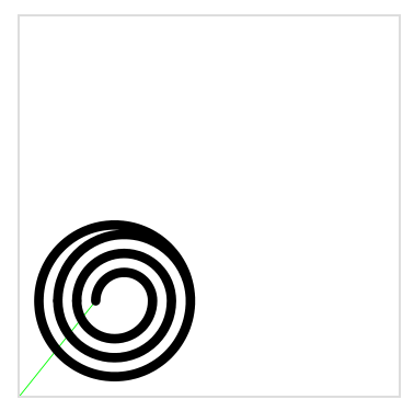
console.log(spiralFull(start, 20, 80, 20, true, 0, true).join('\n'));
// G0 X80 Y100 Z0
// G2 X140 Y100 Z0 I30 J0 F400
// G2 X60 Y100 Z0 I- 40 J0 F400
// G0 X60 Y100 Z0
// G2 X160 Y100 Z0 I50 J0 F400
// G2 X40 Y100 Z0 I- 60 J0 F400
// G0 X40 Y100 Z0
// G2 X180 Y100 Z0 I70 J0 F400
// G2 X20 Y100 Z0 I- 80 J0 F400
// G2 X180 Y100 Z0 I80 J0 F400
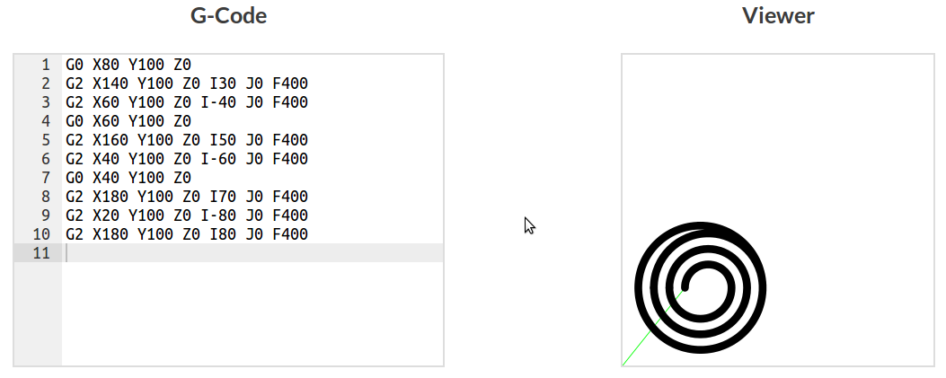
It's important to realise that the line thickness shown in the viewer does not represent the end mill diameter in these examples, but is smaller. This is so the motion can be seen. If it were the correct size to mill a physical hole all that would be visible is a black circle.
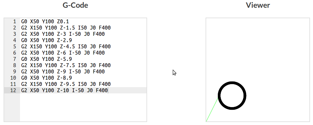
Next a full helical ramping function is create. Unfortunately non of the Z-axis movement can be seen and thus the viewer isn't much use in that respect. Looking at the generated G-code it can be seen that multiple helical movements are created with incremental depths.
function helicalRampFull(center: Pos, radius: number, clockwise: boolean, start_z: number, end_z: number, z_step: number): string[] {
	// generate multiple helical rotations based on the z-step rate

	var commands: string[] = [];
	var rotations: number = Math.ceil(((Math.abs(start_z) + Math.abs(end_z)) / z_step))
	var current_z = start_z;
	var next_z = start_z - Math.abs(z_step);

	// Loop through ramping depths
	for (var i = 0; i < rotations-1; ++i) {
		commands = commands.concat(helicalRamp360(center, radius, clockwise, current_z, next_z));
		current_z = next_z;
		next_z = current_z - Math.abs(z_step);
	}

	// Ramp through left over depth
	commands = commands.concat(helicalRamp360(center, radius, clockwise, current_z, end_z));

	return commands;
}

var start:Pos = { x:100.0, y:100.0 };
console.log(helicalRampFull(start, 50, true, 0, -10, 3).join('\n'));

// G0 X50 Y100 Z0.1
// G2 X150 Y100 Z- 1.5 I50 J0 F400
// G2 X50 Y100 Z- 3 I- 50 J0 F400
// G0 X50 Y100 Z- 2.9
// G2 X150 Y100 Z- 4.5 I50 J0 F400
// G2 X50 Y100 Z- 6 I- 50 J0 F400
// G0 X50 Y100 Z- 5.9
// G2 X150 Y100 Z- 7.5 I50 J0 F400
// G2 X50 Y100 Z- 9 I- 50 J0 F400
// G0 X50 Y100 Z- 8.9
// G2 X150 Y100 Z- 9.5 I50 J0 F400
// G2 X50 Y100 Z- 10 I- 50 J0 F400
Creating the hole, finally
Now functions exist to create spirals and ramps, it should be easy to generate code for cutting a hole. We just need to make use of spiralFull() and helicalRampFull at each pass depth until the full depth has been reached.
function holeNoOffset(hole_location: Pos, end_mill: number, diameter: number, hole_depth: number, pass_depth: number, spiral_step: number, ramp_step: number, clockwise: boolean): string[] {
	var commands: string[] = [];
	if (end_mill > diameter) {
		return ['error', 'end mill too small'];
	} else if (end_mill === diameter) {
		return ['error', 'straight punging required'];
	} else if (end_mill < diameter) {
		var hole_radius: number = diameter / 2.0;
		var ramp_radius: number = (end_mill / 2.0) * 0.9;

		var passes = Math.ceil((hole_depth / pass_depth));
		var current_z: number = 0;
		var next_z: number = current_z - Math.abs(pass_depth);

		commands.push("G90") // Setting absolute coords
		// Loop through cutting passes
		for (var i = 0; i < passes - 1; ++i) {
			// Helical ramp
			commands = commands.concat(helicalRampFull(hole_location, ramp_radius, clockwise, current_z, next_z, ramp_step));
			current_z = next_z;
			next_z -= pass_depth;

			// Spiral out to radius
			commands = commands.concat(spiralFull(hole_location, ramp_radius, hole_radius, spiral_step, clockwise, current_z, true));
		}

		// Final pass at whatever depth is left
		commands = commands.concat(helicalRampFull(hole_location, ramp_radius, clockwise, current_z, -hole_depth, ramp_step));
		commands = commands.concat(spiralFull(hole_location, ramp_radius, hole_radius, spiral_step, clockwise, -hole_depth, true));
		commands.push(`G0 X${hole_location.x} Y${hole_location.y} Z0.1`);
		return commands;

	}

}
Offsets, compensating for the end mill diameter
Using the current code the milled hole will always be oversize by the diameter of the end mill. To compensate for that we just need to specify a hole with the original diameter subtracted by the end mill diameter. A final profile distance is also subtracted so a clean up profile can be run to the exact dimensions.
function hole(hole_location: Pos, end_mill: number, diameter: number, hole_depth: number, pass_depth: number, spiral_step: number, ramp_step: number, clockwise: boolean, final_profile_offset: number): string[] {

	var diameter_offset = diameter - end_mill - final_profile_offset;

	return holeNoOffset(hole_location, end_mill, diameter_offset, hole_depth, pass_depth, spiral_step, ramp_step, clockwise);
}
Final profile
After running multiple passes of ramping and spiraling at different depths there will be faint grooves and marks along the vertical walls. To clean those up a final profile of the hole will be run. This is why a small distance was subtracted from the hole size earlier. The code generated will run the end mill at the full depth around the radius of the hole.