
Published: 26-04-2016
Overview
The design apps goal is to generate G-code to run a CNC machine. The basic idea is to have a MCAD library for creating the model and an MCAM library for creating toolpaths. The model and toolpaths should be viewable. This is a rather large piece of work and so will be broken down into smaller chunks. A good and useful starting point is the G-code viewer, starting with just 2D.
Software Stack
Same as the makeit-workshop app. It use nodejs and express on the backend. Angular 2 is used on the frontend. Gulp is used for high level control of build processes, i.e. typescript compilation and stylus -> css.
App components
The 2D G-code viewer will enable a preview of G-code paths before running the CNC machine. This helps check the G-code for errors and geometrical clashes. To start, the app is split into four basic components. The main component is bootstraped and contains the menu, ace-editor and viewer components.
General mechanics
Ace is used as the embedded editor, hence the ace-editor component name. When a change is detected in the editor an output event is triggered sending the new text value to a method on the main component. The main component then 'parses' the text and updates an object which is automatically re-rendered in the visualiser component. The visualiser component is an SVG element. Using the SVG 'viewbox' attribute all the objects draw can be scaled to the size of the machine.
Straight lines
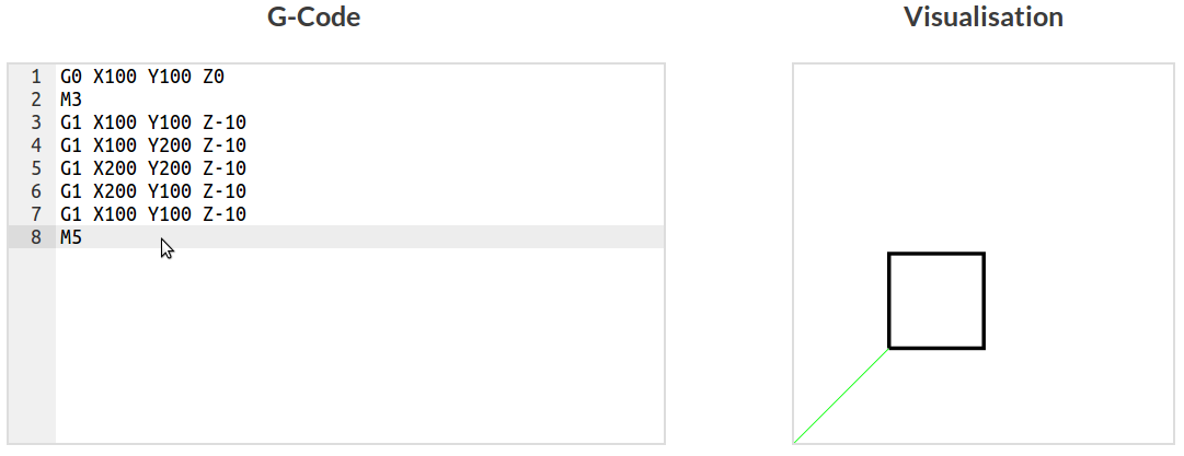
Converting G-code lines to SVG line is trivial. The X and Y coordinates are simply stripped from the G-code command and fed into an SVG line command. For example, starting from 0,0, G1 X10 Y10 in G-code becomes M0,0 L10,10 as an SVG path.
The complication comes from splitting the paths. We don't want to see G0 'rapid move' commands as if they were G1 'cutting commands', so we need a different line colour. A different line colour requires multiple paths. To achieve this we loop through all the Gcode commands and append successive G0 or G1 commands together in a path. The paths are then coloured independently. This requires an extra variable to keep track of the machines current position so the initial 'M' can be set in each new SVG path.
The origin in SVG is the top-left corner which might not make sense from a CNC point of view. This is easily reversed by subtracting the max Y-axis length by the value. This positions the origin in the bottom-left corner. Setting the path stroke width allows a cutter dimension to be simulated.
Arcs
To do anything useful arcs are needed. These form the basis of holes and also curves (sometimes). In G-code arcs are described by end points and either the centre or a radius. Common convention seems to favour the centre based option. Apparently using radii can cause error magnification along the arc for a given end point error. An arc command in G-code might look like this:
$$G2 \ X \ Y \ Z \ I \ J $$
'G2' specifies the arc is clockwise, 'G3' would be used for a anti-clockwise. 'X' and 'Y' set the arc end points. 'Z' can be used to create a helix by creating an extra linear motion in the Z-axis. That will be addressed later, for now it's just a 2D arc. 'I' and 'J' specify the center in the X and Y axes. This is all in the XY planes. Planes can be changed using the G17-19 commands.
SVG arc commands are centre-based only. It's important to remember that arc in both G-code and SVG start at the current location. SVG arcs are specified like this:
$$A \ RX \ RY \ P1 \ P2 \ P3 \ X \ Y $$
'A' specifies that this is an arc command. 'RX' and 'RY' are the X and Y radii, which means the arc could be elliptical rather than just circular. 'X' and 'Y' are the arc end points. Parameters 'P1', 'P2' and 'P3' set properties of the arc. 'P1' is the x-axis-rotation and is rarely used. 'P2' is the large-arc-flag and specifies whether the small or large arc should be drawn. 'P3' is the sweep-flag and control the direction the arc is drawn in. Setting 'P2' to 0 draws the small arc while setting 'P3' to 1 specifies the clockwise direction.
To make practical and simplify the conversion, only small arcs will be drawn. The sweep-flag will be determined by the use of 'G2' or 'G3'.
An example - circle quadrant
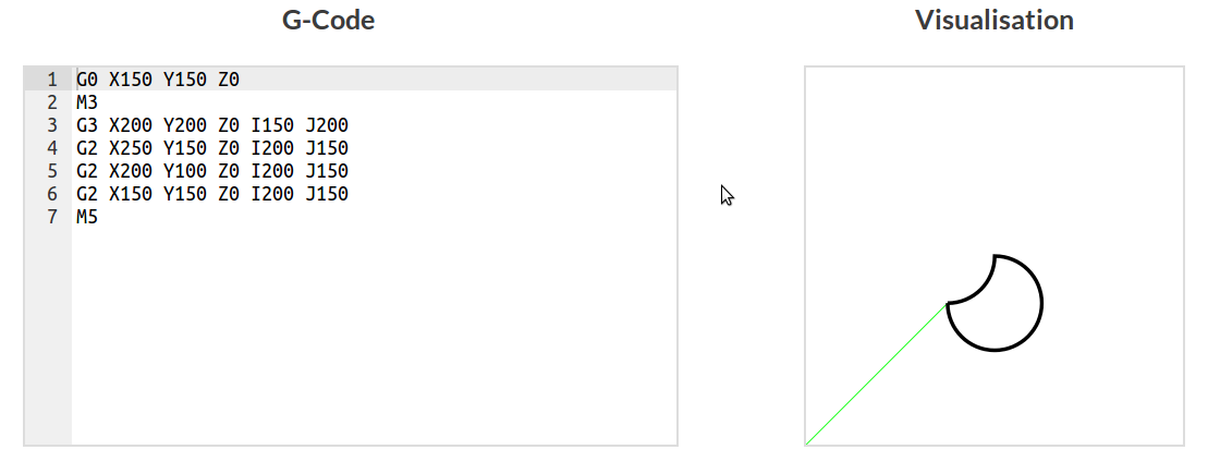
As an example here's arc for a circle quadrant. The left example starts at 0,0, ends at 50,50 and has a radius of 50. The right example is the same but has an anti-clockwise direction. Offsets ares used in the image to make it look pretty but the commands will ignore that. The example also uses the non-standard SVG bottom-left origin following the app.

Left quadrant:
$$G2 \ X50 \ Y50 \ Z0 \ I50 \ J0 $$
$$A \ 50 \ 50 \ 0 \ 0 \ 1 \ 50 \ 50 $$
Right quadrant:
$$G3 \ X50 \ Y50 \ Z0 \ I0 \ J50 $$
$$A \ 50 \ 50 \ 0 \ 0 \ 0 \ 50 \ 50 $$
As can be seen all that changes is the sweep-flag in the SVG command. Some might also notice that the arc is not strictly mirrored in the y-axis by locating the origin. This is because the arc still tries to draw the arc clockwise or anti-clockwise.
Conversion
To convert between the G-code and SVG the radius must be calculated from the centre point and the current position. If the current position is X,Y and the centre I,J. This is as simple as:
$$radius = \sqrt{abs(X-I)^2 + abs(Y-J)^2}$$
Warning: this may cause 'false positive' arcs as there are multiple ways of obtaining the same radius. This happens when I and J are reversed. Note that the same radius is set to both 'RX' and 'RY' for a circular arc. The end points can placed in the correct location without modification. The sweep-flag is set depending on whether 'G2' of 'G3' was used.
Using lines and arcs
Drilling holes on a CNC machine can be done several ways. One of the best is helical ramping. The G code command for helical movement is the arc command with a Z-axis movement specified. This is neat because our arc visualisation will automatically ignore this Z movement just showing the X AND Y movement when parsing the G-code. This means we can visualise a fairly complex helical motion in 2D without any modification.
Helical ramping is commonly used as it allows various hole sizes to be milled with a single end mill (that's smaller than the hole). This technique is supposedly less intensive on the end mill than plunging or straight ramping. Often helical ramping is used to a certain depth and then the end mill is spiraled out to the hole diameter. This is repeated for the entire depth of the hole. A finishing profile might then be cut on the full depth of the hole. We can create and visualise this with the 2D visualiser. This technical is also used to 'pocket' cut material.