Published: 23-08-2016
Overview
Currently the design app isn't quite finished, but it can do some stuff. Over the passed month I've learnt a lot more about JavaScript and actually writing software in general. I starting making this at the same time I starting learning JavaScript and Angular, so it was bound to be full of rookie errors and badish coding practises. Its time to analyse it and figure out how to take it to a more professional level.
Design App
The design app is used to create geometry and generate G-code to manufacture that geometry.
CAD Functionality
Currently
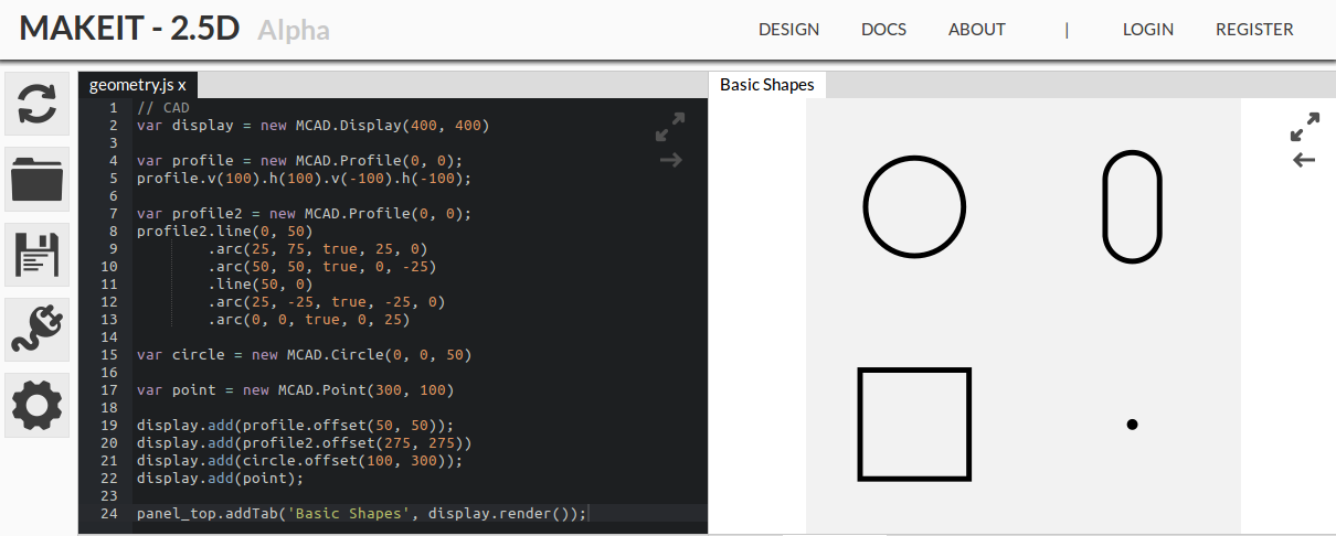
The CAD library provides tools for creating basic geometry such as points, circles and profiles. Profiles consist of line and arc segments. Geometry is represented by objects which have access to chainable methods. The methods let you perform operations like offset and shift. The idea was to minimise the amount of effort/typing needed to create geometry. The 'classes' that construct the geometric objects require the new keyword which is easy to forget and bit clunky. Returning objects with methods attached allows for very user friendly chaining, but maybe it limits the flexibility a bit. It is the object-oriented approach to creating geometry. Here is how you create geometry:
Maybe?
A functional approach might be more interesting and flexible. In a functional approach the geometric objects would be represented by pure geometric data and not self-encapsulated functionality (no methods or inherited methods). Using this style, the data could be serialised and made truly universal thanks to JSON. You could generate geometry in languages other that JavaScript should you wish. Basic primitives could be grouped together to make models, which could also be grouped. Transformations could be applied in a functional way for rendering and conversion to G-code. The conversions for rendering and G-code are already somewhat functional but not separated from the class based objects.
CAM Functionality
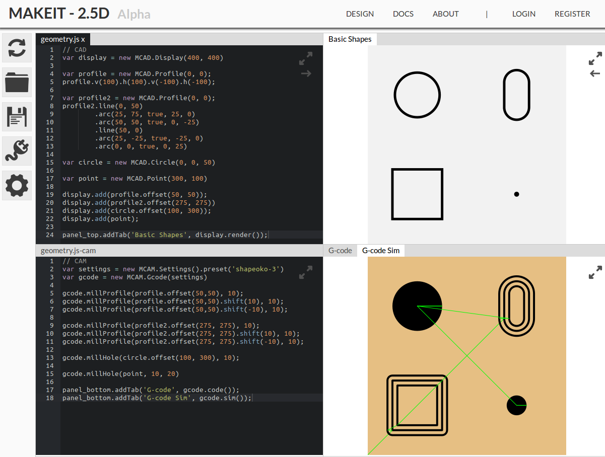
The CAM library operates much the same way as the CAD library. There is a public 'class' G-code, which indirectly exposes classes for converting and rendering geometry. Geometric objects can be added either individually or as an array. Using the previous geometry, CAM operations can be generated and simulated. The code should be fairly self explanatory:
Panels
The panel class is exposed to the user through panel_top and panel_bottom. It lets them add visual content with labeled tabs to the panels. The addTab accepts a DOM element and renders it to the screen. It seems to work pretty well and adds a lot of viewing flexibility.
Multi-window Syncing
Multi-window syncing works, but is primative. When a change is made to the code, the editor calls a method on the Angular filestore service with the updated code. The code is sent via socket to the server which broadcasts it to all other connections. The server also 'processes' the change by adding it to a collection of open files. It determines whether the virtual file is open already and then acts accordingly, either creating it or updating it. The same happens on the receiving clients. They are distributed in a sense and all perform the same algorithm during an up update. Here's a look at it working:
Keeping multiple windows in sync means the app can be used across multiple screens, whether on the same computer or not. Panels can arranged and maximised to the users preferences. Not many CAD programs support multi-screen layouts let alone unlimited screen layouts. The GIF below shows an example demonstrating customisation of the panel layouts.

The syncing isn't just useful for multi-window layouts, but should also enable collaborative working and customer viewings. There are a few things to get done before that becomes possible though.
This very basic system works well for a local or home setup (local server) because there is (generally) no latency and a single server. It would work fine for a home based small machining setup. For use as a general app hosted on the web much is left to be implemented. The socket implement requires a decoupling pub/sub system so it can be run across multiple servers. This wouldn't be too hard to implement using redis. To counteract latency issues operational tranforms should be used on the code changes. Operational transforms help resolve conflicts when the document is being edited in two places concurrently. Only the changes should be broadcast not the entire document as currently is the case.
Version Control
Version control is partially integrated currently. The Git backend service is able to get statuses, create repositories, add and commit files. The main missing feature is the ability to roll back to previous commits. Commits only happen when the data is saved, until then it is just kept in sync with the server and other windows. Below is an examples of the file changes being logged:
Importantly the files changes for commits are also synced between multiple windows. This means saving can occur on any window in use.
File browser
The file browser is activated by a clicking on the side menu 'folder' icon. It pop ups to cover the full left side of the page. It allows the user to navigate the users filestore. Each user has a filestore which can host multiple Git repos. Each Git repo represents a project. The file browser looks like this in action:
The file browser was/is tricker to implement than a typical file browser. The reason for this is that it hides certain details from the user. Each part or component is actually made up of two files, the CAD (geometry) file, and the CAM (manufacturing) file. Every time a new file is created, it's actually two files. The same goes for saving, committing and rendering them. For example, when a user creates my-part.js, it is translated to my-part.cad.js and my-part.cam.js on the file system. It makes the file browser code a more complicated.
There is good reasoning behind splitting up the CAD and CAM functionality. Defining the CAD and CAM separately but for the same part forces you to design for manufacture. Larger models must be split up into parts that can be manufactured in one go, or close to one go. It also means you can determine whether a commit has changed both the manufacturing and geometry or just one, making changes easier to understand. It manages the separation of concerns nicely. Either side can be ignored while working on the other without one big confusing file. The alternative is leaving it to the user to decide to a nice file structure.
The mapping between a single part and two files is current baked into the file browser which is undesirable. When refactored it should be changed so there is a one-to-one mapping. The implementation should allow a middleware process to be defined for certain file types which takes care of this special mapping. This would make the file browser a useful reusable Angular component for other projects.
The client side code does not have to check whether the folder is a Git repo, this is done on the server. The client needs to know whether a folder is a repo so it can determine where a user can legitimately create a new repo. You can't have a repo in a repo, but you can have repos in nested folders.
Plugins
Plugins aren't implemented yet and I'm not sure how they should be implemented. The simplest way to implement them would be to state that everything in the file should be wrapped in a function with the same name as the plugin. When using a plugin the file code can just be concatenated onto the current code file and accessed through a function call. This works fine in the browser but prevents any future use in an environment like node. Really a proper module format like CommonJS should be used.
The plugin browser is just another instance on the file browser component, only pointed at a plugin directory. Each user will have a private area for plugins. They will be able to make a plugin available to others by publishing it.
Documentation
There is a documentation page but it leaves a lot to be desired. The main documentation is really these logs. They explain some of the implementation, but don't do much to explain the API and how to use it. The next iteration of this project will first involve setting up a new system for documenting and testing. Documentation and testing are the backbone of a project and this prototype is somewhat spineless, that will change.
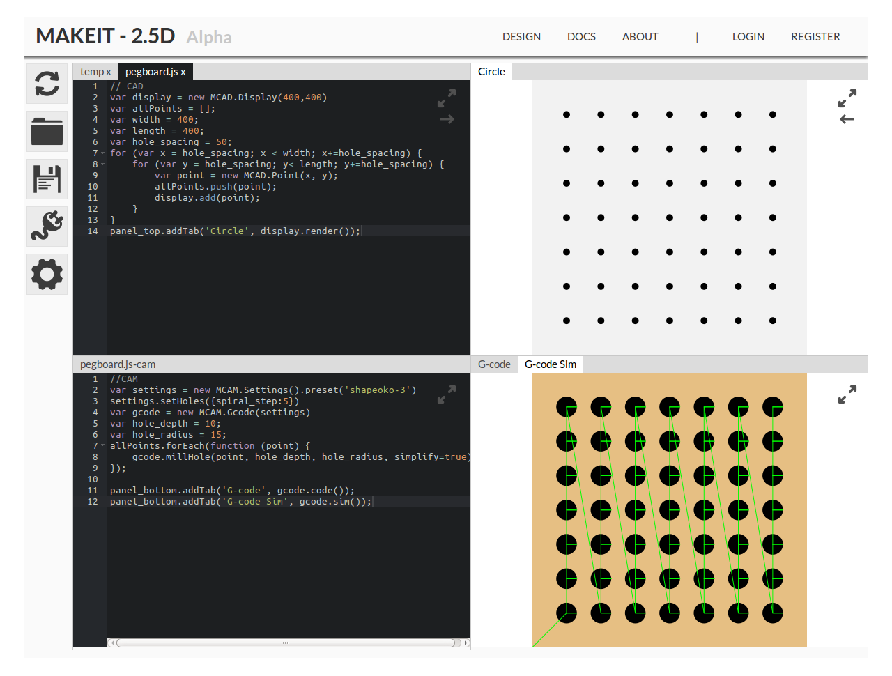
Pegboard Example
Below is the pegboard example used in some of GIF above. It serves as a very basic demonstration of how easy it is to design and generate G-code for repetitive tasks using this system. Use of variables to hold important dimensions make the model fully parametric. The same example could be produced with circles instead of points.
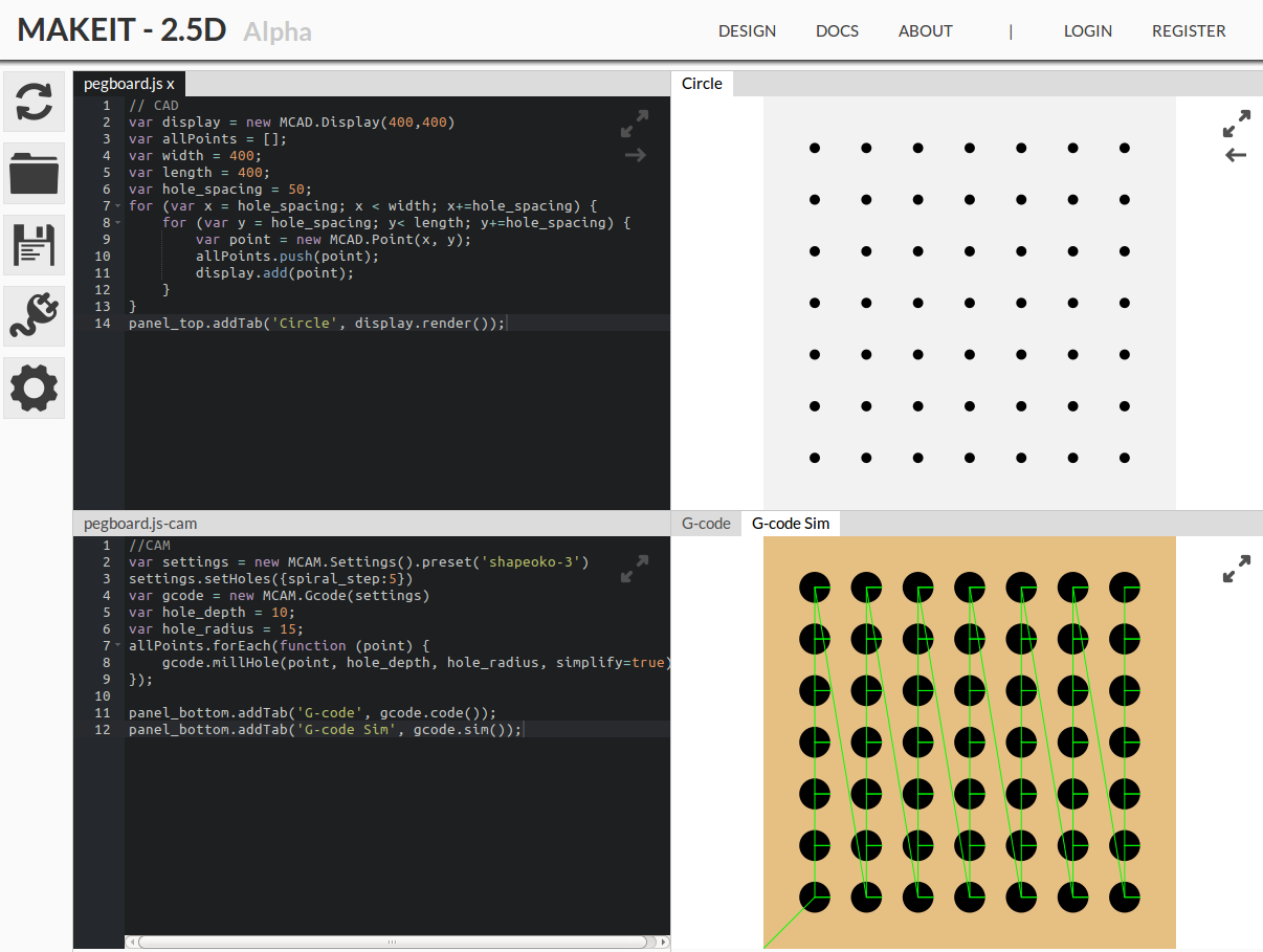
When the geometry is updated the CAM code is also re-run automatically re-calculating all of the G-code commands for the new geometry. The G-code produced is over 16,000 lines long, which shows just how much effort goes into making some holes. This is because holes are milled using helical ramping and spiral cutting, as explained in an earlier article. Although this is a simple example, it goes some way to explaining the potential of the system.
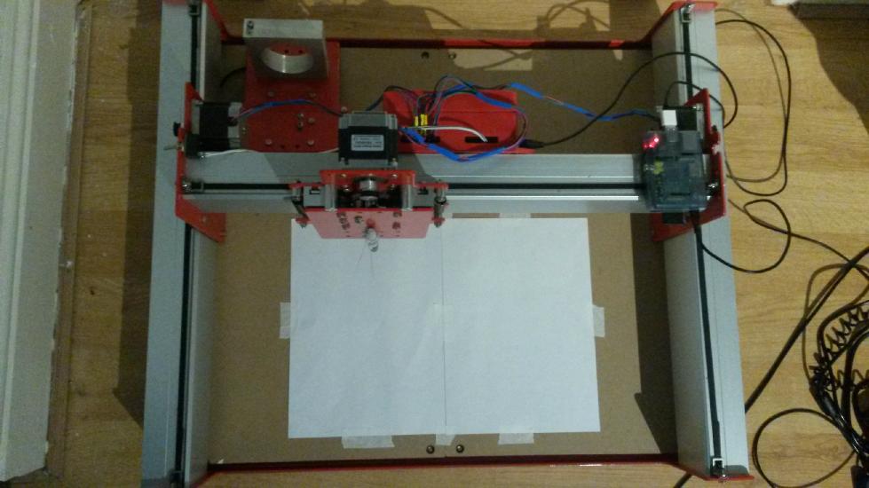
Workshop App
The workshop app runs off a Raspberry Pi. The server doesn't load on startup by default yet, but it's easily done. The app still uses an old Angular 2 beta and needs porting to the latest version. It currently looks like this:
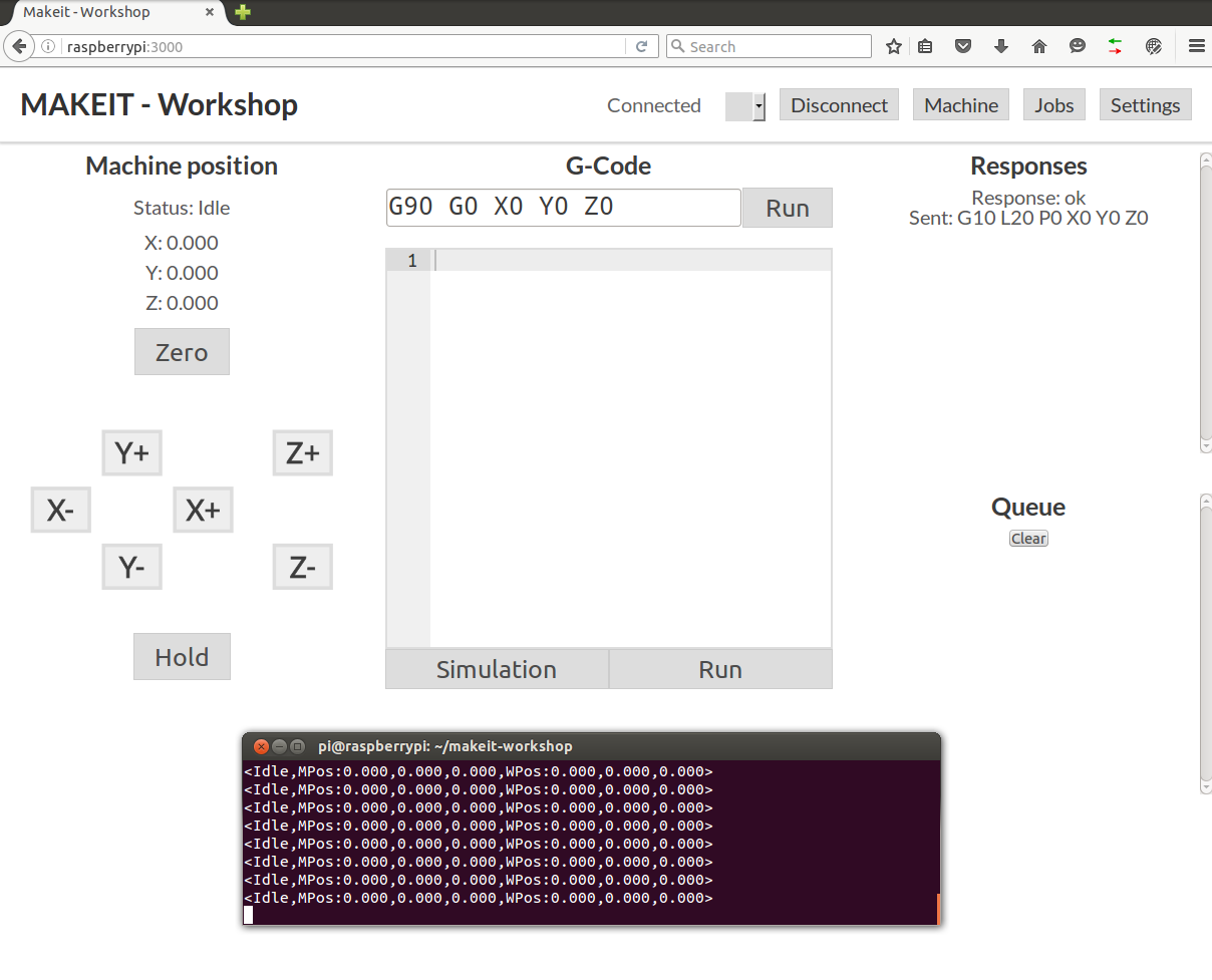
Everything works okay until a cable gets pulled out and it disconnects. When there is a connection error the server crashes. The server needs to catch the error and notify the user that something happened and the connection was lost. It also needs to have some way of knowing where it was before the error so it can restart safely. A conservative method might be to:
- 1) Record the line position of the last item sent
- 2) Move back up the code by the GBRL buffer size and set this as the start point
- 3) Re-zero the machine, like at start-up
- 4) Move to the start point position and run the code
Some of the commands in the buffer might have been run, or even blocked by a single arc command. Starting from a full buffer retract means commands may be re-run, but this won't cause any problems because there is nothing to cut.
A Shapeoko 3 is the test machine of choice at the moment. It's a 3 axis machine running GRBL. The app should be able to control any machine compatible with or running GRBL. I believe the Smoothie boards have a GRBL mode making them compatible. The reason Smoothie boards are mentioned is because they are available with up to 5 axis control, this makes them attractive for future CNC machines, where a fourth or fifth axis may be needed (hot wire cutter, 5-axis CNC).
Full Example
As an example the design and workshop apps will be used to create and plot a few simple shapes using a marker pen (I can't spin up a spindle in my flat). Below are two very simple profiles, a square and slot.
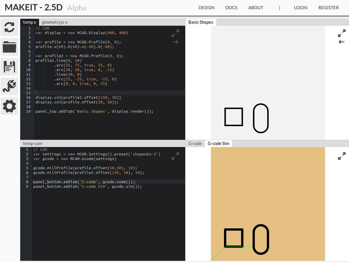
The two profiles are converted into the G-code for milling a profile (the machine will simply follow the path). Below is the generated G-code:
G90
G0 Z15
G0 X50 Y50 Z15
G1 X50 Y50 Z0 F400
G1 X50 Y110 Z0 F400
G1 X110 Y110 Z0 F400
G1 X110 Y50 Z0 F400
G1 X50 Y50 Z0 F400
G0 Z15
G90
G0 Z15
G0 X150 Y50 Z15
G1 X150 Y50 Z0 F400
G1 X150 Y100 Z0 F400
G2 X175 Y125 Z0 I25 J0 F400
G2 X200 Y100 Z0 I0 J-25 F400
G1 X200 Y50 Z0 F400
G2 X175 Y25 Z0 I-25 J0 F400
G2 X150 Y50 Z0 I0 J25 F400
G0 Z15
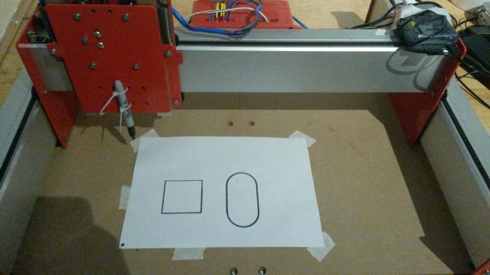
The G-code can be entered in to the workshop app and away it goes. Before starting the G-code run the machine is zeroed at the bottom left corner, touching the base. I will try and make a video at some point, it just looks a bit rubbish on my phone.
After a couple of minutes the drawing is done. Yes, a couple of minutes is slow, but it was setup to cut wood.
So there it is, a small run through. Although it didn't do anything complicated it's nice to have an end-to-end system working. Granted, a lot of things don't work as well as they should, and there are a lot of features to add. For a prototype it proves that this could be pretty cool. Fast forward a while and hopefully there will be a 3D version cutting out a whole host of exciting projects.
References