Published: 22-12-2015
This section takes a look at the first composite panel we manufactured. The first panel was more for practise than anything else. It was to make sure we knew what we were doing when resin infusing and testing the panel. Fibreglass was chosen over carbon for cost reasons. There was no point risking any lovely carbon fibre for a test run. Aluminium honeycomb was used as the core material. This post walks through the steps used to make the first fibreglass panel and test it. It also contains a lot of things that are later changed because they didn't work very well.
Manufacturing sandwich panels
Step 1 - An aluminium plate measuring 700mmx700mm was used as the mould. 3 layers of release agent were applied to the surface allowing each individual coat to dry before applying the next.
Step 2 - Layers of biaxial (+-90) fibreglass cloth weighing approximately 900 gsm were cut to 600mm squares. 3 layers were cut with orientations of 0/90, +45/-45 and 0/90. The 3 layers of fibreglass were placed on the mould after the release agent had dried.
Step 3 - A layer of peel ply was placed on top of the final layer of fibreglass. The peel ply overlapped the fibreglass by roughly an inch. The peel ply is used to create a bondable surface to aid in attaching the honeycomb core.
Step 4 - Infusion mesh was placed over the peel ply. the infusion mesh was slightly smaller than the fibreglass squares (roughly an inch). Tacky tape is placed around the perimeter of the mould.
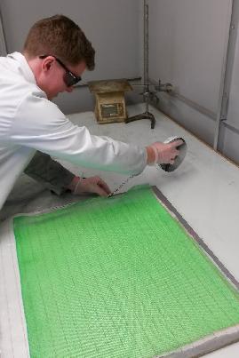
Step 5 - The resin inlet and vacuum tubes were added at opposing edges approximately at the centre of the mould. The infusion mesh is wrapped around the inlet tube. ‘Ears’ were formed with tacky tape around the tubes and opposing sides.
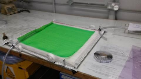
Step 6 - The catch bag for excess resin was made next. First breather cloth was cut and placed inside a double over vacuum bag. The lower valve half and catch tube were placed in the bag before being sealed with tacky tape (leaving a gap for the catch tube). The valve was placed at the opposite end to the vacuum line.
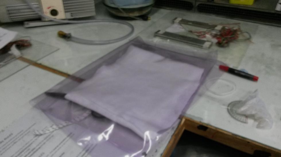

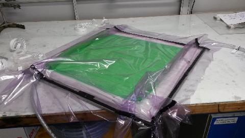
Step 7 - The vacuum bag was cut to size and carefully placed over the mould stuck down with the tacky tape. This proved tricky and a few ‘rucked up’ areas (lower right corner in picture) may have contributed to the vacuum bag leaking later on in the process.
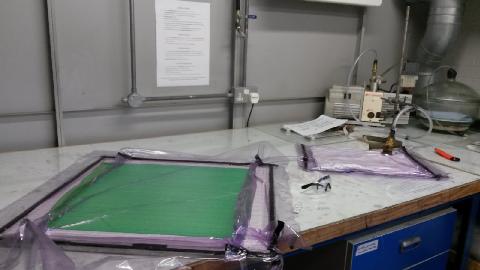
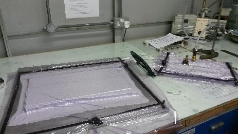
Step 8 - The mould and catch bag were then joined by the catch tube and completely sealed. The bags were then checked and “fiddled with” until all noticeable air leaks were detected and stopped. The leaks can generally be heard. Clamping the vacuum line, turning off pump for 15 minutes and then re-checking is also good practise. The complete setup is shown below.
Step 9 - The amount of epoxy resin was then calculated, measured and mixed. The resin tube was placed in the cup of resin and unclamped allowing the resin to flow into the layup stack and infuse the fibres.
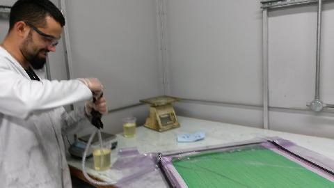
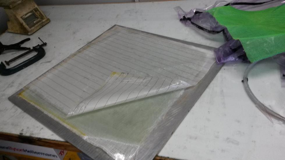
Step 10 - Once fully infused the resin inlet was clamped. Unfortunately a leak managed to develop through the vacuum bag and the vacuum pump could not be let overnight as the resin was too close to the outlet valve. The next morning the consumables were removed exposing the laminate.
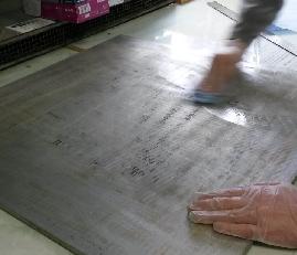
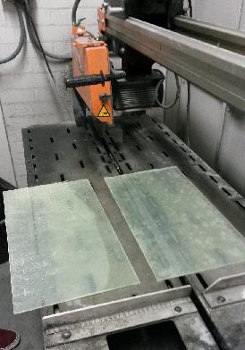
Step 11 - The laminate was cut to the specified dimensions (500mm x 275mm) using the large cutting machine.
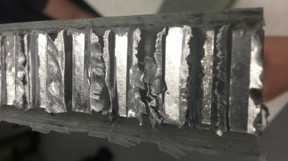
Step 12 - Next the aluminium honeycomb core was expanded from it’s delivered state. This proved tricky. Eventually one end was screwed down to piece of wood and the other pulled while standing on the wood. This caused quite a bit of distortion around the edges, however due to the excess width and length this didn’t pose a problem.
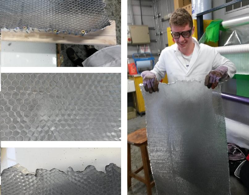
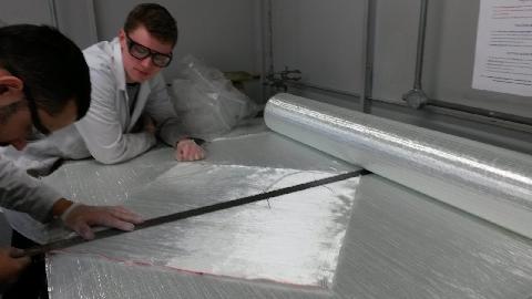
Step 13 - The honeycomb was cut (using scissors) slightly larger than the final panel size to help with vacuum bagging and trimming of the final part.
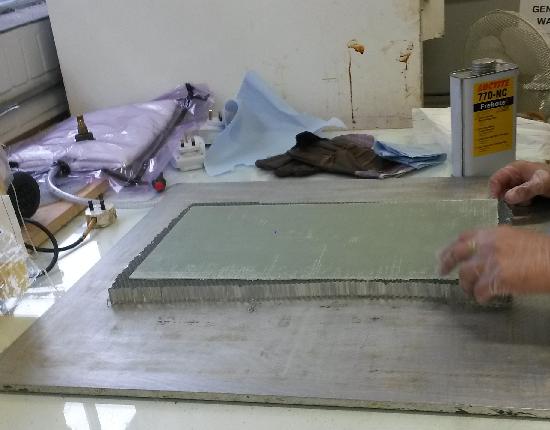
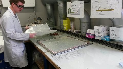
Step 14 - The fibreglass facesheets were bonded to the honeycomb using epoxy. The epoxy was spread over the facesheet using a wooden stick. Peel ply and breather cloth (doubled over) were layered on top of the panel. The panel was then placed under vacuum using the same technique as before. Although not probably needed a leftover catch bag was used in case epoxy was squeezed out of the panel.
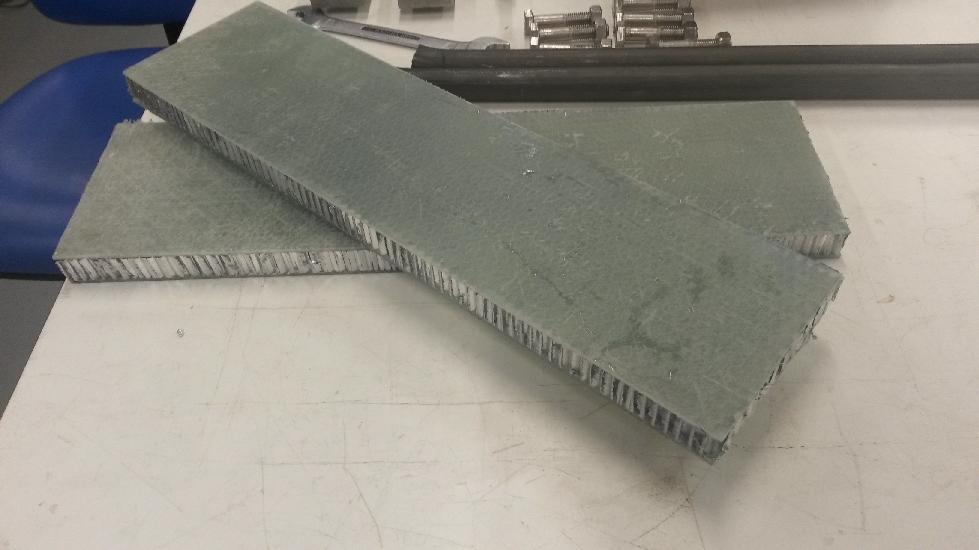
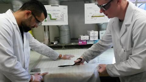
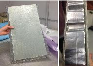
Step 15 - The single panel was halved creating two test pieces. An issue arising from the bonding was that in some locations the fibreglass had not set onto the honeycomb, specifically in a couple of the corners. This could be due to air entering the vacuum bag or not spreading a uniform layer of resin onto the facesheets.
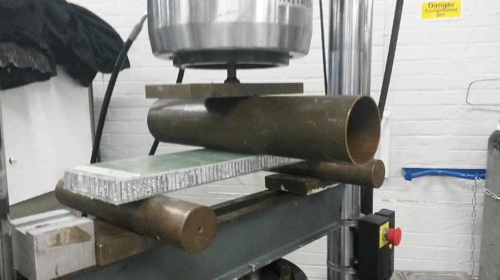
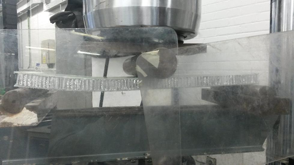
Testing sandwich panels
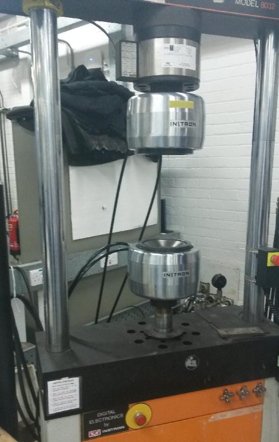
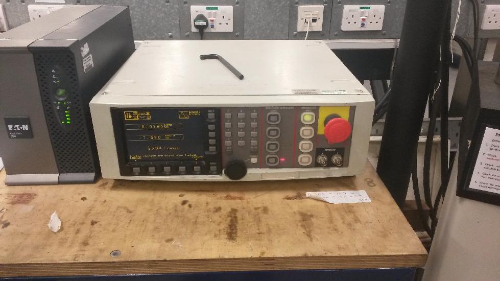
The two manufactured panel were used to carry out a 3 point bending test. The test was not carried out exactly as per the rules as the test rigs had not been finished. The idea was to become familiar with using the machine and data logging equipment. The machine used is shown in figure 16.