Published: 27-12-2015
Foam Cutting
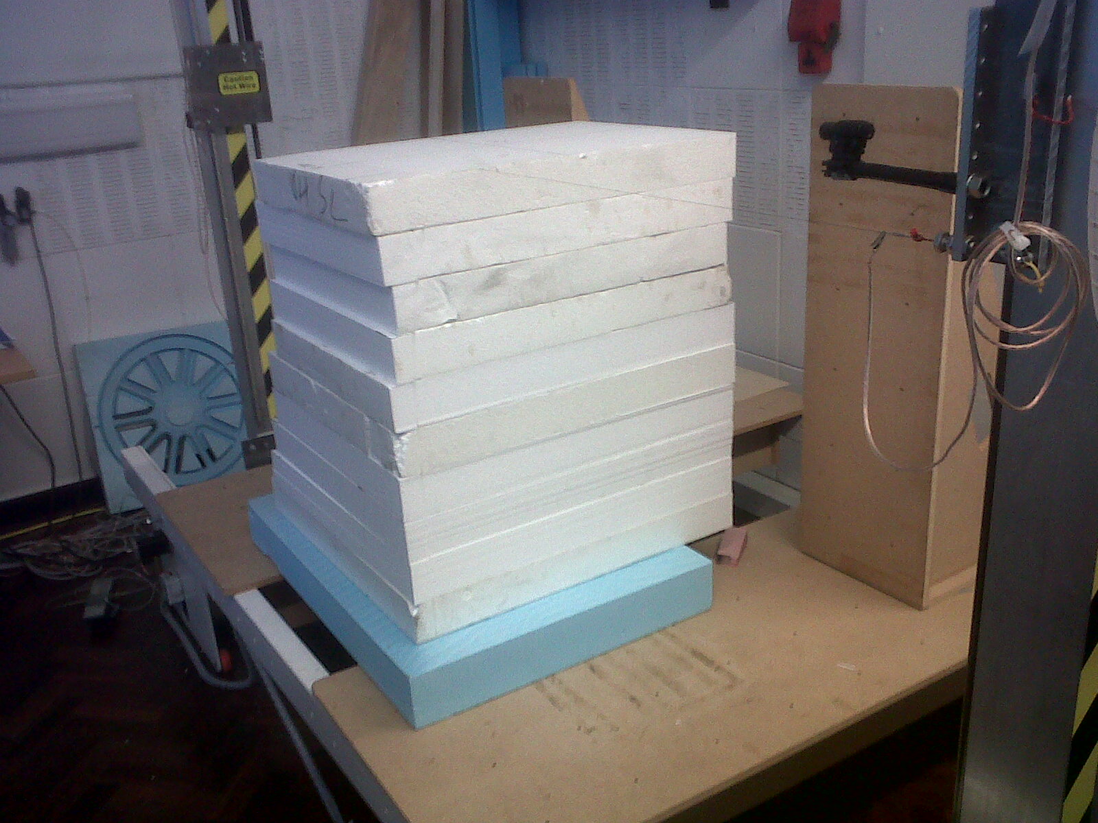
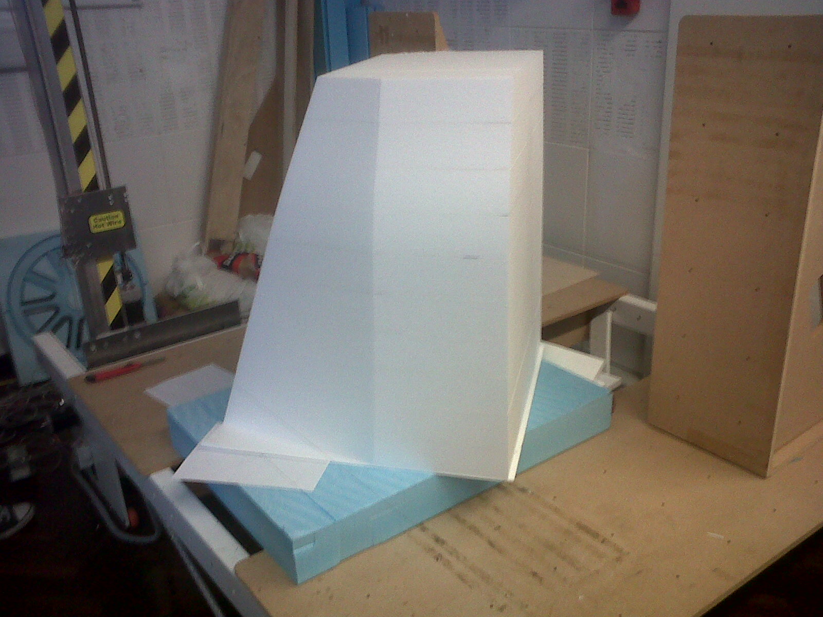
2D drawings (generally DXF files) were created from the 3D part. In order to cut out a part with complex curvature several views and angles had to be taken. I.e. normally the side and top views are cut along a with views at rotated angles for more detail. The filleting and smoothing of edges is done by hand using templates (to ensure the correct shape). To build up the volume of foam required to cut the shape several pieces may be placed on top of each other making sure no glue will come into contact with the hot wire (generally glue is not needed, they can be rested on top of each other).
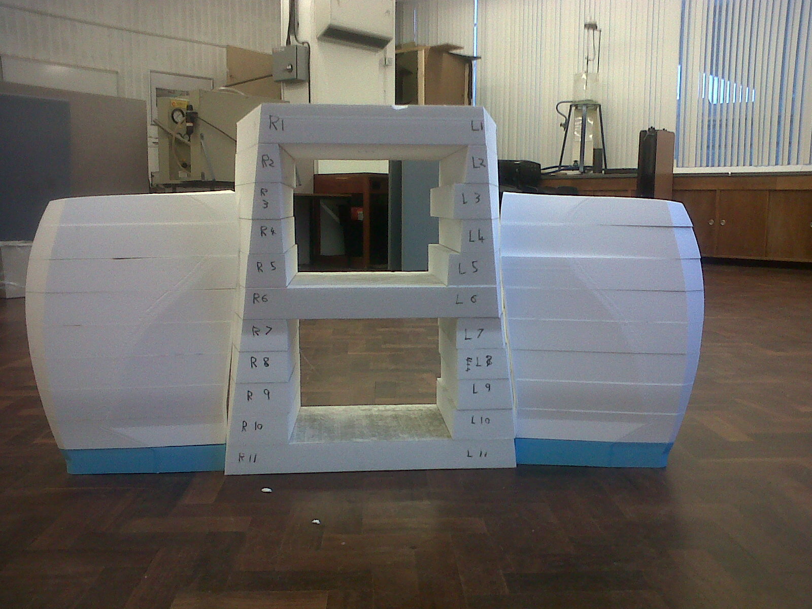
The most effective and easiest way is to buy large foam blocks (8x4x2ft) and avoid joining thinner sheets together. The drawings must all have the same reference point so that the CNC machine can be calibrated correctly when the foam is rotated or moved. Cutting thin foam sheets lengthwise should not be attempted as the foam with have a tendency to curl and deform in thinner areas when the heat is applied. When splitting up a large object to be cut try to keep free flowing parts together and cut as bigger sections as physically possible. This will lead to fewer alignment errors and mismatches between interfaces. The following pictures show how the sections were split up on the 2014 car. Ideally the nose and front section should have been done as one piece. After the shape had been cut the sections of foam were separated and glued together using Jesmonite acrylic resin.
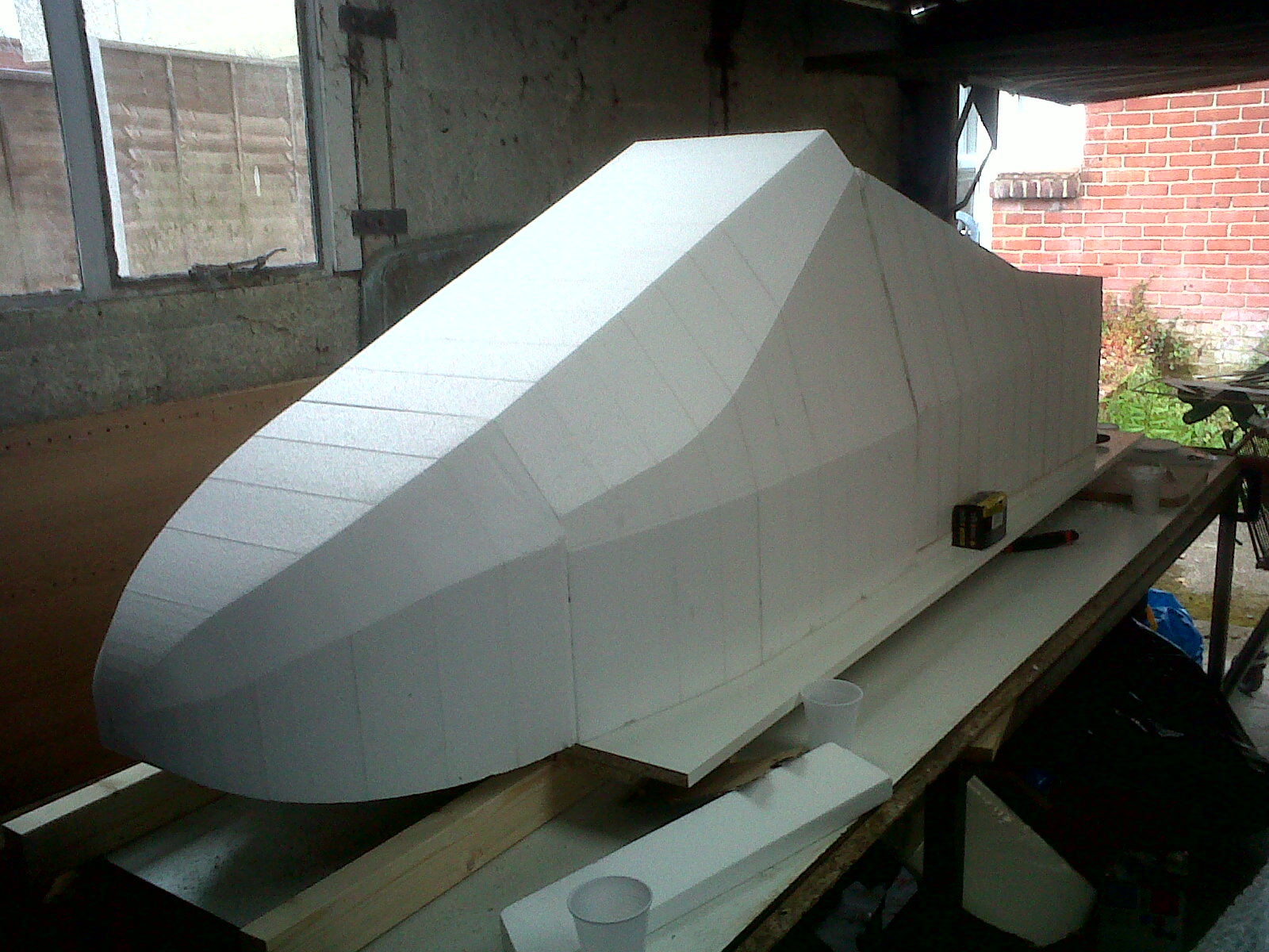
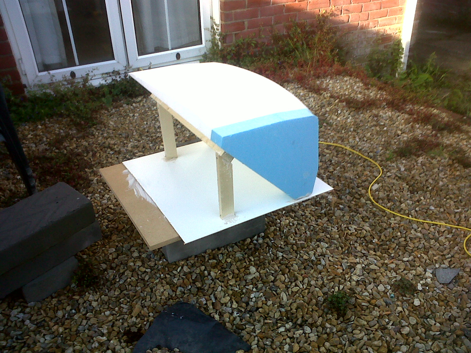
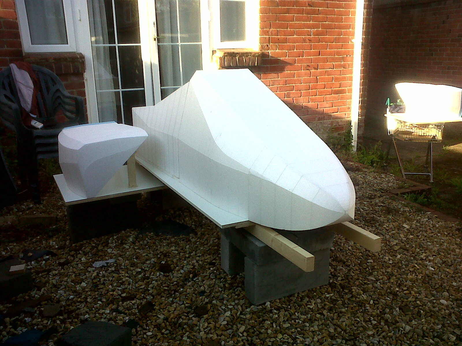
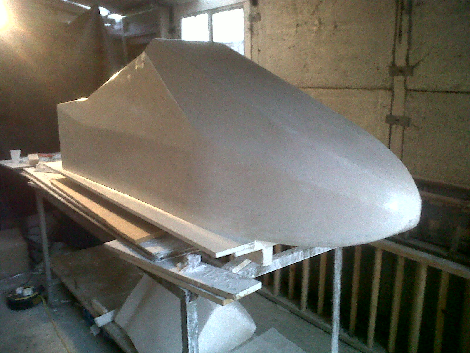
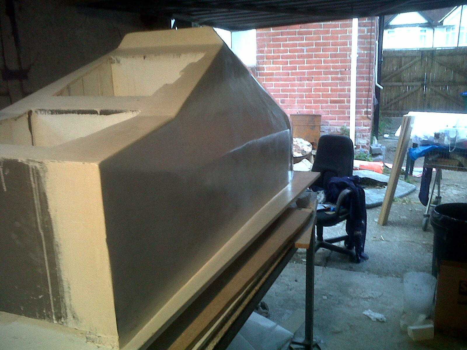
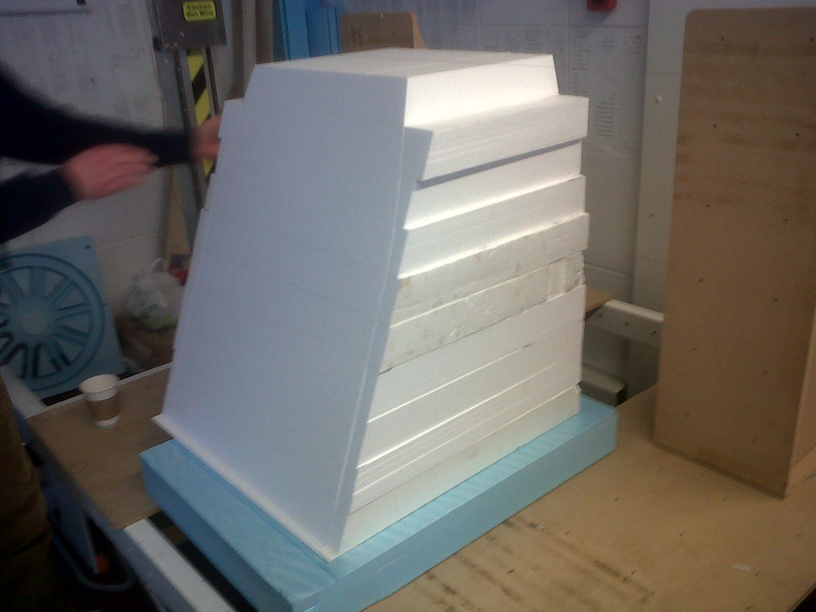
The following images show the foam for the front section being cut and then fixed to the nose to create the front of the car.
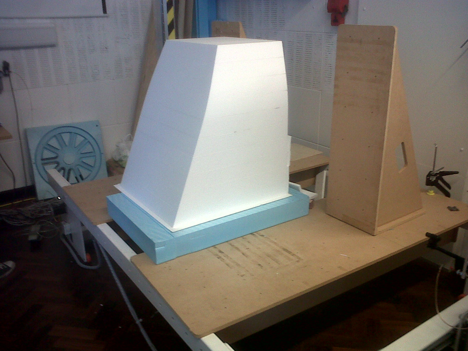
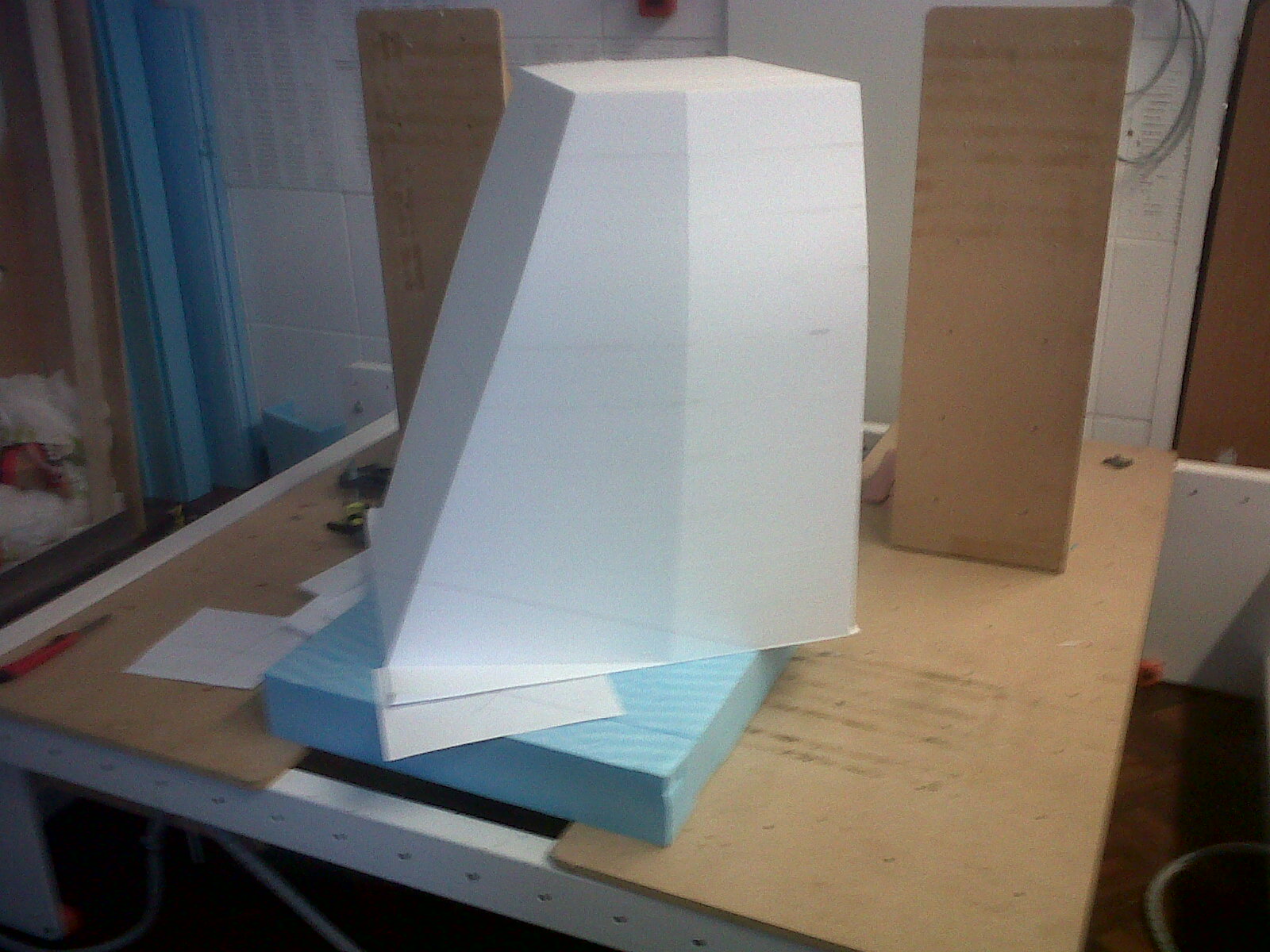
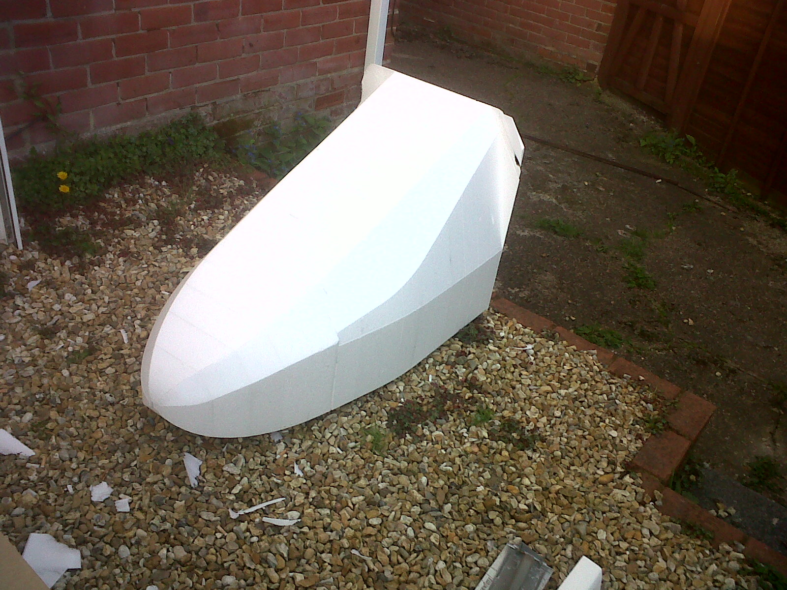
After the shape had been cut the sections of foam were separated and glued together using Jesmonite acrylic resin. Templates had been made according to the CAD design (laser cut) and were used to guide the hand shaping of the sharp edges and rounded corners. Sanding along the length of the car (in the direction of airflow) is beneficial to prevent ripples in the surface and ensure a nice flowing shape. All areas of sending and filleting were marked before carrying out the work to make sure the correct amount of material was removed.
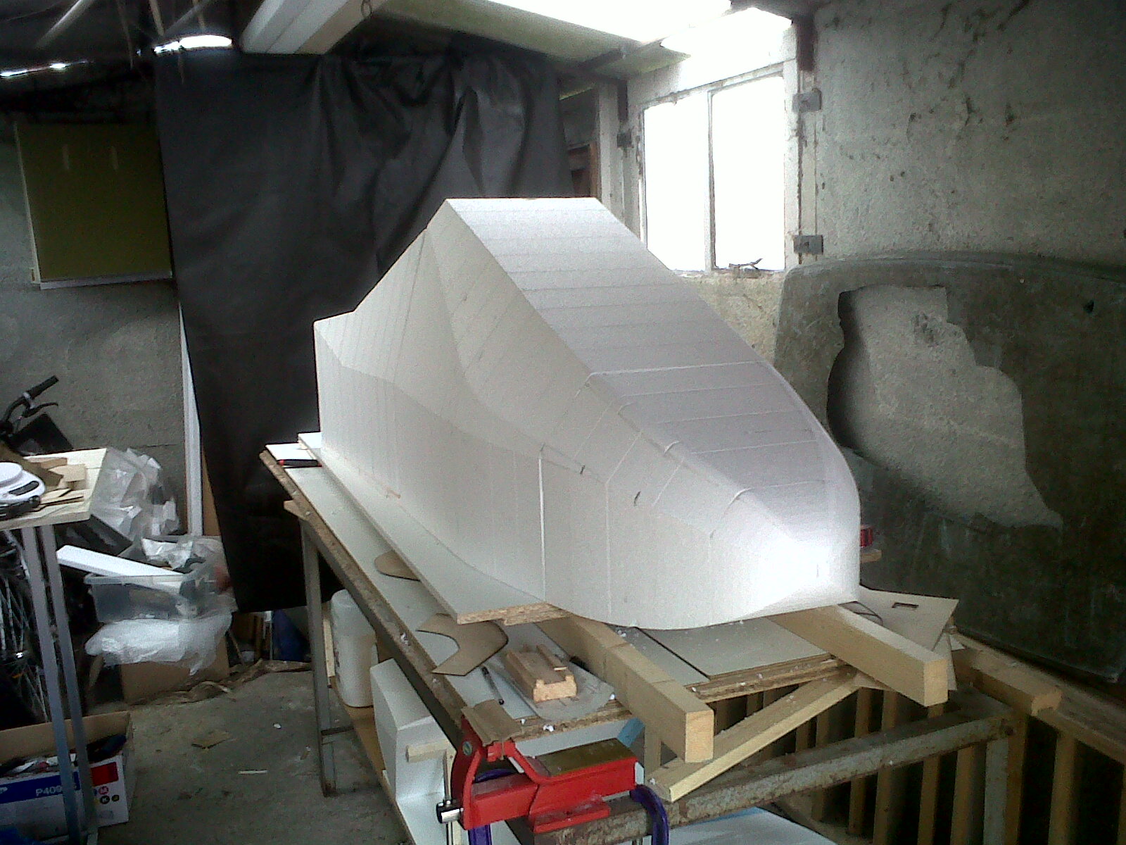
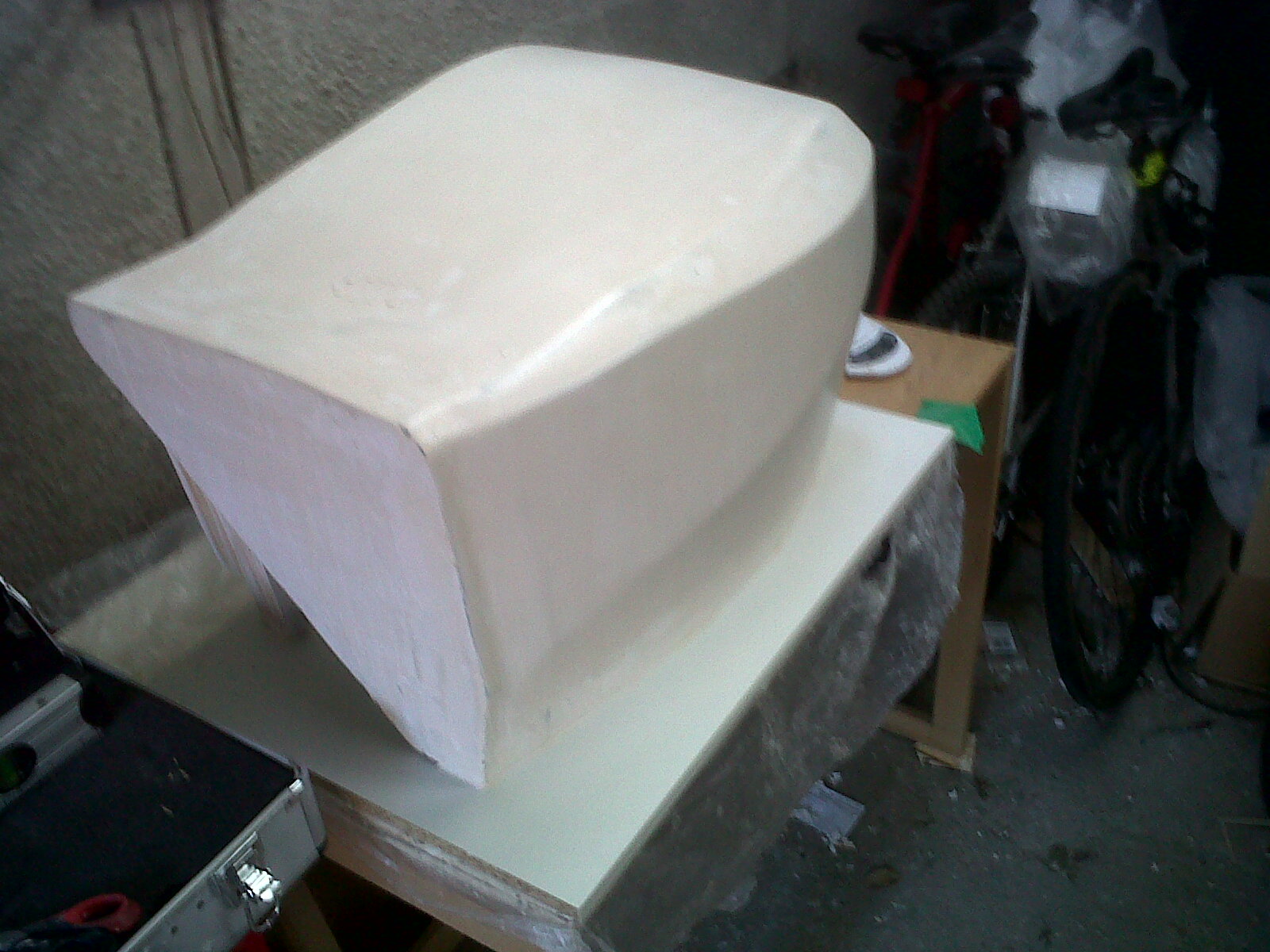
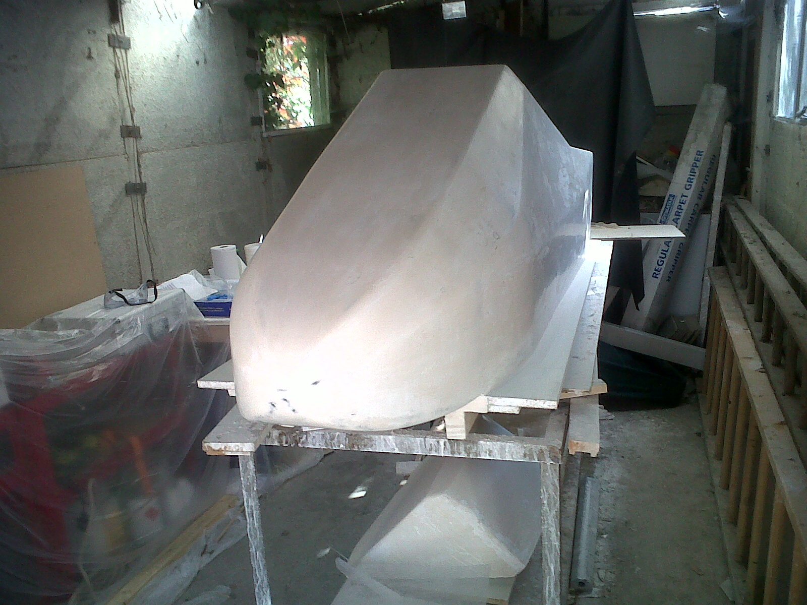
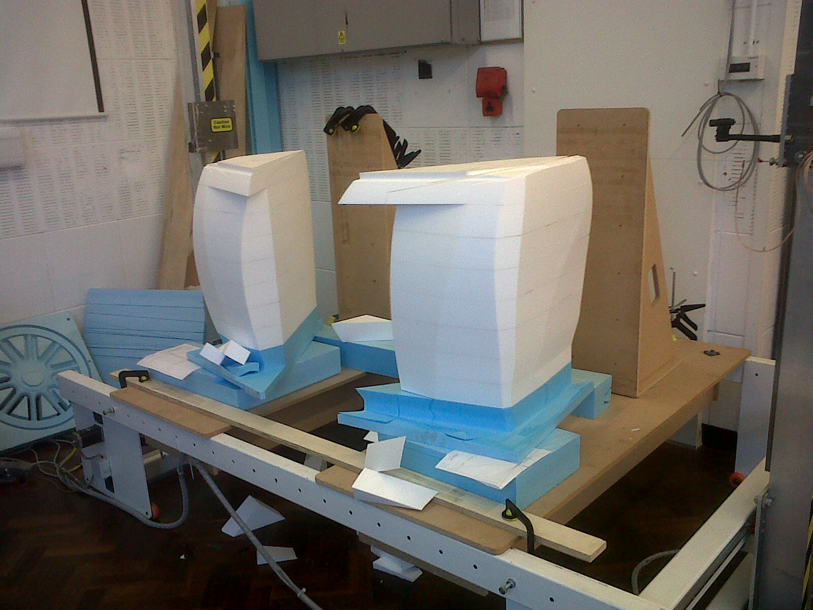
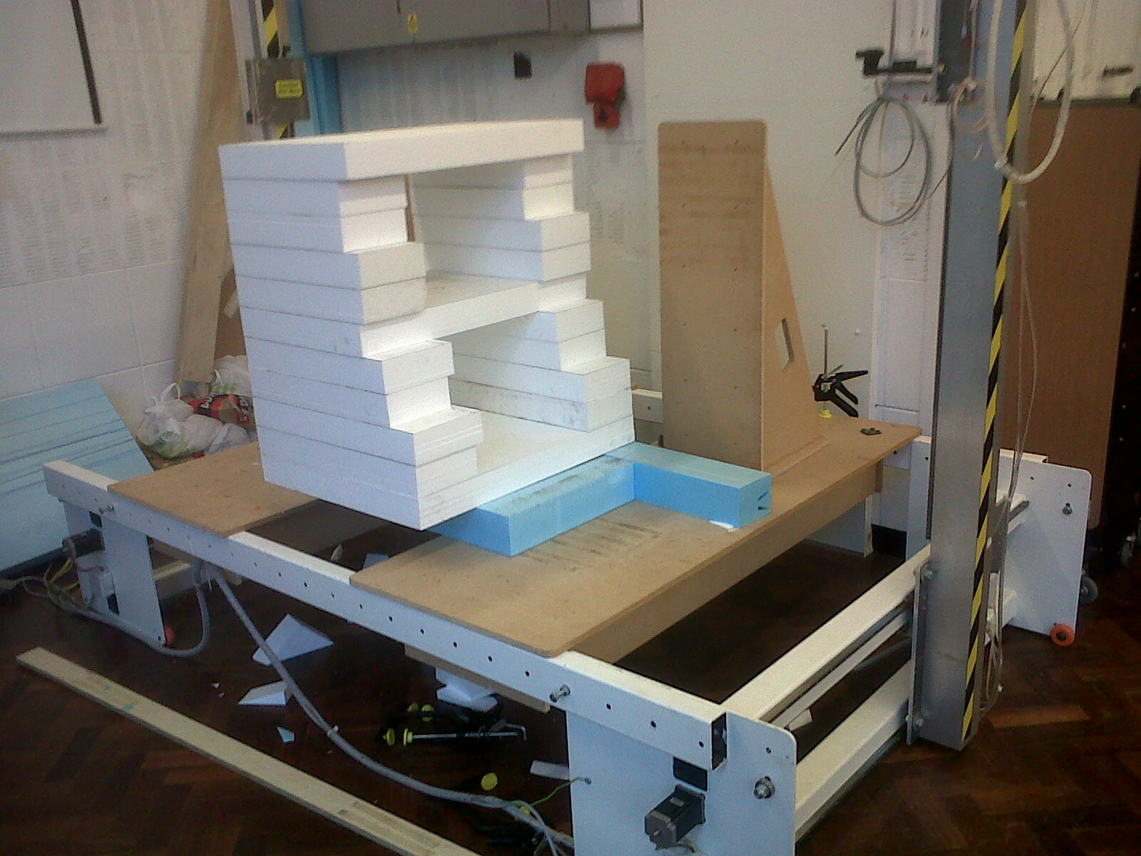
Some pictures of the middle section and sidepods being cut:
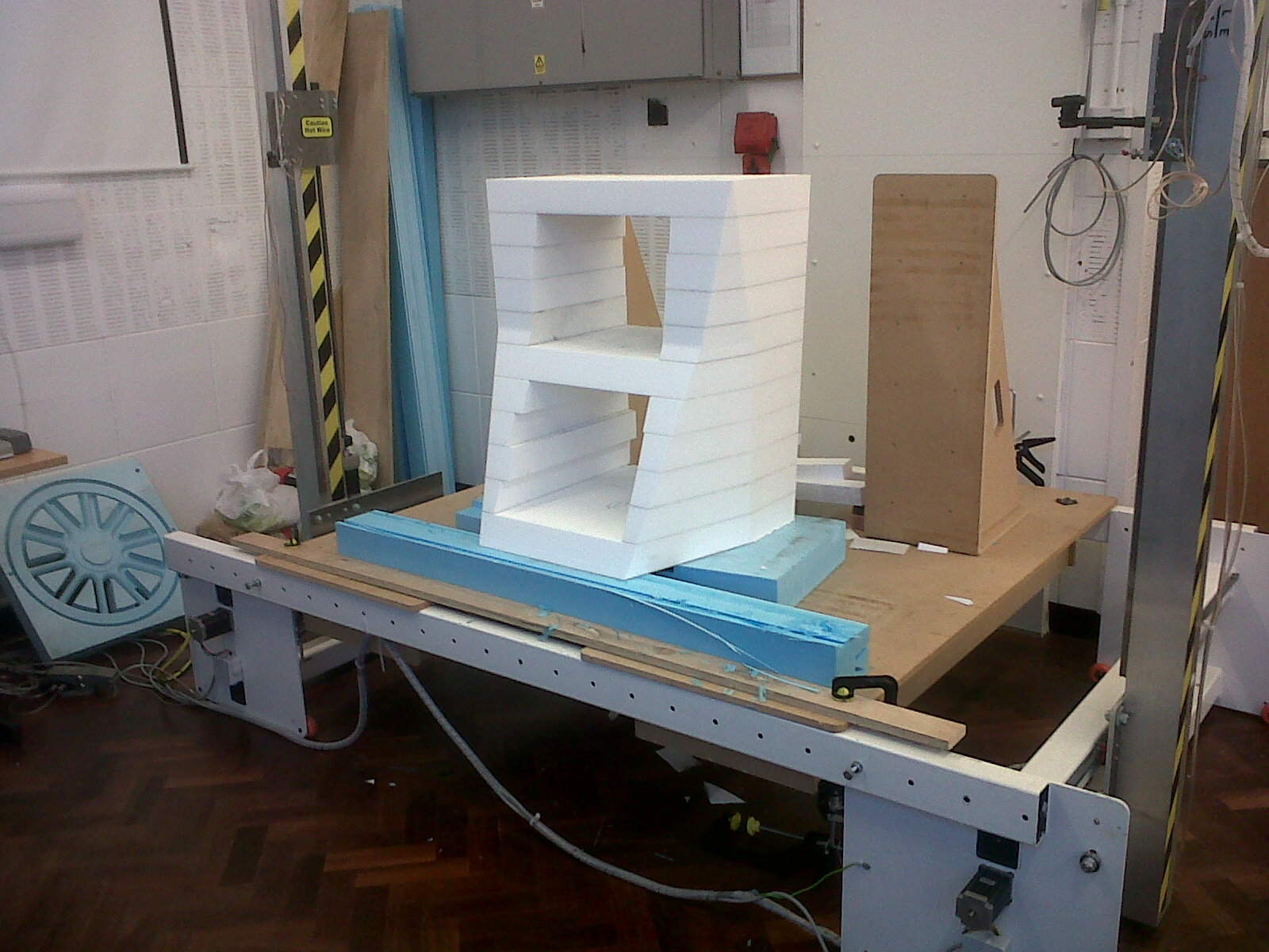
Once the body had been sanded to the final shape the first layer of jesmonite was added. The base coat was thickened using thixotrope and dyed using black pigment. This was done to help identify the first layer when sanding through subsequent layers of jesmonite. After the first layer was applied the highs were taken of by wet sanding. This was done not to long after the jesmonite had set solid (30 minutes) making it easier to sand as it had not reached its full hardness. Finally pinholes and other imperfections were filled in to help create the smoothest surface possible. A single light source helps identify areas of imperfections (due to the shadows created).